
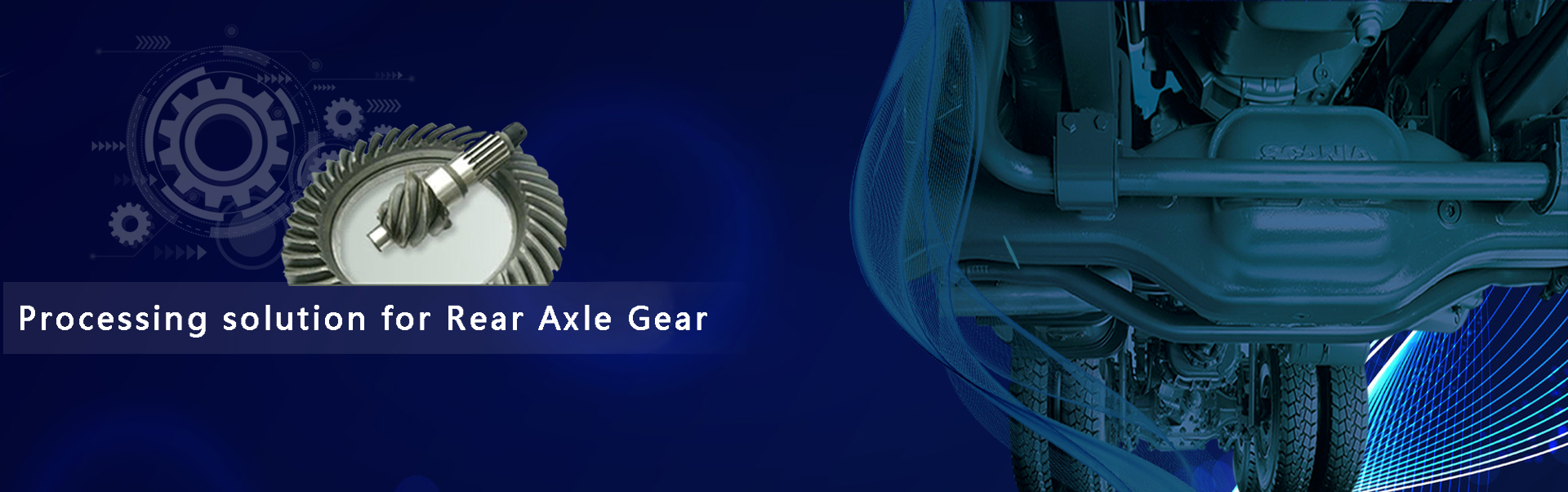


Rules for Installation and Debugging of Gear Drawing Machine
Machine Tool Lifting
Before unpacking, the number of boxes should be checked to confirm whether the number of boxes is correct. After disassembly, confirm with each other whether the appearance of the equipment and its components are normal and non-destructive. If there is a problem, record the scene in time and contact the company so as to deal with the problem quickly and minimize the impact on the installation and debugging process. After unpacking, find out the packing list and attachment form immediately, check all the items carried in the packing box with the customer, and hand over the signature (if there are special items such as inspection mandrel, please specify the storage requirements).
When lifting, it is necessary to explain the lifting position of the equipment to the customers so as to select the lifting mode, understand the weight of the machine tool and select the appropriate lifting equipment. When lifting, care should be taken not to damage the mechanical parts and external protection of machine tools.
Check and adjust machine tool level
Inspect the appearance, accessories and external electrical and hydraulic lines immediately after the equipment is in place. If the crane causes damage, please confirm with the customer immediately.
Know the power grid situation of workshop from customers to ensure the normal connection between power grid and equipment. According to the power of machine tools, help customers to choose the correct connection diameter, type and size of the switch and grounding mode. If there is pneumatic equipment, the customer should prepare the gas source according to the use requirements.
Ask customers to prepare oil for hydraulic, lubrication and cooling according to the instructions.
When adjusting the level of the machine tool, in order to adjust conveniently, the pad iron of four corners of the machine tool can be placed first, and the pad iron of other parts can be placed after the adjustment is completed. When the level adjustment is finished, the other parts of the machine tool should be put in place, including electrical cabinet, hydraulic box and chip removal device. When installing, attention should be paid to the corresponding number of each component with the number of the machine tool, so as to prevent errors.
Connection Method of Hydraulic Box and Chip Remover
The oil pipe of the hydraulic tank is connected by the installation mark. The circuit is divided into two parts: the power line (U, V, W) and the pressure relay. Dial-to-dial connection is enough.
The tubing of the chip remover is fastened by a throat hoop, and the power cord U V W can be connected by number.
Connection of Electrical Cabinet Circuit
Wiring Method of YH6140/YH6240 Driver
Facing Electrical Cabinet and Driving Module
The connection of the orange line below the module is as follows:
SP | X | Z |
The green line above the module can be connected with the orange line.
The plug of YH6240 cam encoder has notch guide and can be inserted well.
White wires are connected above the power module near the outermost interface
Wiring Method of YH6150/YH6250 Driver
Facing Electrical Cabinet and Driving Module
The connection of the orange line below the module is as follows:
Z | ||
SP | X | Y |
The green line above the module can be connected with the orange line.
The line of YH6250 cam encoder is the same as that of white line and YH6240.
Power-on preparation and start-up debugging
General power supply of machine tool, ground wire connected according to requirement
Remove the fixing block of the X-axis of the machine tool.
(YH6150/YH6250 In addition to loosening the X-axis fixing block, the four clamping cylinders of the Y-axis should be loosened half-circle, and then the top wire should be tightened.)
Before power-on, all electrical circuits of the equipment should be checked once to confirm whether there are leakage, misconnection and loosening, and check whether the voltage of the electric cabinet's inlet line is normal (380V +10%) with a multimeter. At the same time, all oil and gas circuits should be checked whether they are connected properly, and whether the hydraulic, cooling and lubricating oil levels are correct. The above mentioned items can be checked and confirmed before power on.
Check the direction of hydraulic box, cooling pump and chip remover motor after power-on is completed.
After starting the hydraulic system, the system pressure and branch pressure should be checked according to the instructions.
Check the time and flow setting of timing quantitative lubrication system.
Call out the program in the program list to run the hot car
|

 086-022-24981179